Sunday, March 7, 2010

The Concept of Green Building

Green Buildings are Eco Friendly Structures

When the pre historic man constructed a hut for the first time using bamboo trees and coconut leaves to protect himself from sun and rain, he was starting to exploit nature for his humble needs. Apart from killing the trees he also disturbed the natural habital of the insects and birds in those trees and interfered in the cycles of nature. That was a beginning.

Now, it is beyond imagination, how much damage has been inflicted on earth by the construction of various types of buildings using sand and water from the rivers, stones from the mountains, cement manufactured from the ingredients dug from the land. In addition, carbon emission from the buildings and manufacture of construction materials warm up the air and space.

But, after getting conscious about the environment and after feeling the environmental responsibilities, the way our people try to address this problem is wonderful. One of the intelligent initiative is the concept of “Green Buildings”.

The concept of Green Buildings envision a new approach to save water, energy and material resources in the construction and maintenance of the buildings and can reduce or eliminate the adverse impact of buildings on the environment and occupants.

By preferring Green Building over a conventional building we help this planet earth and the people to retain nature to a maximum extent possible in three ways with reference to the location of the buildings.

1. Retain the external environment at the location of the building.
2. Improve internal environment for the occupants
3. Preserve the environment at places far away from the building

Green Buildings Retain the Environment at the location of the Building.

Suppose we propose a multistoried office complex to accommodate thousands of officers and staff, it requires a vast area. Therefore selection of a site for such a building complex should consider retention of local vegetation, wild life, natural water courses etc. Either a site with bio diversity should be avoided or the building should be planned to reduce site disturbance.

Land :The landscaping and the exterior design in a green building shall be in such a way that there is more shaded area, the light trespass is eliminated and local species of plants are grown.

Water : The green building by its design and shape shall not disrupt the natural water flows, it should orient and stand just like a tree. Rain falling over the whole area of the complex shall be harvested in full either to replenish the ground water table in and around the building or to be utilized in the services of the building. The toilets shall be fitted with low flesh fixtures. The plumbing system should have separate lines for drinking and flushing. Grey water from kitchenette, bath and laundry shall be treated and reused for gardening or in cooling towers of air conditioning.

Energy: The solar energy at the top of a green building is harvested to supplement the conventional energy,. The natural light is harvested in the intermediate floors to minimize the usage of electricity. Sunlight is restricted by the high grown trees outside the lower floors of the building. High efficiency light fixtures make a pleasant lighting apart from saving the energy. High-efficiency windows and insulation in walls, ceilings, and floors are used for the benefit of better temperature control.

Green buildings improve internal environment for the occupants

Light: In a designed green building the occupants shall feel as if they are in outdoor location. The interior and exterior designs shall go hand in hand by blending the natural and artificial lighting and presenting transparent views wherever possible.

Air: In the air conditioned environment, a green building shall be specially equipped to ensure the Indoor Air Quality for a healthy atmosphere. Even the nasal feelings shall be pleasant free from the odour of paints and furnishings.

A comfortable atmosphere at work stations improve the attendance of the staff and increase the productivity.

Green buildings preserve the environment at places far away from the buildings.

We all know that a building is constructed using cement, sand, steel, stones, bricks, and a lot of finishing materials. These materials are quarried or procured from far way from the location of the buildings. Building materials are responsible for about 20 percent of the greenhouse gasses emitted by a building during its lifetime,.

Green buildings shall use the products that are non-toxic, reusable, renewable, and/or recyclable wherever possible. Locally manufactured products are prefered so that the collective material environment of the locality remains a constant and moreover the fuel for the transport of materials is saved.

As we see, our food and domestic products are tagged with green as a fashion of eco friendly practices, building materials are also going green. The futuristic green buildings are to use green materials which are in research stage now.

Green wood : A Stanford team has done a research for wood alternate. Hemp fibers and biodegradable plastic when pressed together and heated form layers and this material is as strong as wood. When buried in land fill, it degrades faster. This wood creates more raw materials when it breaks down. Microbes produce methane gas when they decompose this wood substitute and other debris thrown into landfills. Another type of bacteria absorbs this gas and turns it into plastic that can be used to create a new wooden plank. By this cycle, there is a continuous source of raw material for this wood. When this material at research comes to market, it may help to control deforestation and promote the rainfall.

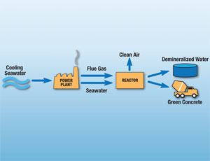
Green Cement: Bruce Constantz at Calera, based in Los Gatos, has developed a green method to produce both cement and aggregate, another component of Concrete. Their method sequesters Carbon Di Oxide from power plant flues and mixes the gas with sea water to produce the mineral raw materials of concrete. For every ton of green cement Calera manufactures half a ton of fly ash from coal plants is used apart from preventing production and emission of Corbon Di Oxide.

Other Green Building materials: Renewable plant materials like bamboo (because bamboo grows quickly) and straw, lumber from forests ecology blocks, dimension stone.recycled stone, recycled metal are some of the other materials used in a Green Building.

LEED GREEN BUILDINGS RATING SYSTEM

The Buildings constructed based on the Green concepts should confirm to the prescribed standards. There should be continuous assessment and and monitoring from the planning/design stage upto the completion of construction, for declaring a building as a Green Building.

For this, LEED ( Leadership in Energy and Environmental Design ) Green Building Rating system is followed. In this system points are awarded for adopting Green concepts in various categories and the Buildings are certified Green at levels such as Silver, Gold or Platinam based on the total number of points they get in LEED Rating.

Measurement / Audit for Green Concept in Buildings

Categories for Rating LEED points
Sustainable site 12
Water efficiency 8
Energy and atmosphere 17
Material and resources 13
Indoor Environment Quality 15
Design process and innovation 4
Employing LEED designer 1
Total points 70

Certification for Green Buildings

Level Points required
LEED Certified 26 to 32
Silver Level 33 to 38
Gold Level 40 to 52
Platinam Level 53 and above

There are only few Certified Green Buildings in India. But it is good to know that the awareness is gathering momentum and we look forward for a greener future.

Unpolluted Water, Soil, Mountains and thick Forests
are the Forts defending a Land

( ThiruValluvar 742)

Written by Malarthamil on the eve of observing World Environment Day on June 5


read more...

Sunday, February 28, 2010

New Green-Concrete Process Combines Seawater, Flue Gas


(Las Vegas, Nevada) -- Cement scientist Brent Constantz wants concrete to be the
"hero" that cleans up dirty coal. "The reality is, coal is not going away," he says. "We
need to meet the world’s power demands without emitting more carbon." His answer? A
new type of concrete that sequesters carbon without disturbing its traditional binder:
portland cement.

This past summer, the Stanford University professor’s Los Gatos, Calif.-based startup,
Calera Corp., began making cement from flue gas and seawater at Dynegy’s gas-fired
1,500-MW Moss Landing Energy Facility. At first, Constantz hoped to replace portland
cement, which emits about one ton of carbon dioxide per ton produced. But after some
industry pushback and more research, he now says he can use Calera aggregate
synthetic stone, sand and gravel to capture CO2 and still produce net gains.

Constantz cemented the new course in Las Vegas on Feb. 3 appropriately, on the first
day of this year’s World of Concrete show speaking to 100 world-leading scientists and
engineers during a 90-minute seminar. In the packed room, Constantz, who owns more
than 70 patents for medical cement, assured the group that Calera could be used to
replace portland though it is not essential. "The way to get it accepted is probably
through the aggregate," he says. (In Las Vegas, Constantz said he can use aggregate
to store carbon in concrete.)
The pitch worked. Florian Barth, a structural engineer and incoming president of
American Concrete Institute, says Calera "has great potential." The seminar "was
promising," adds Steven Kosmatka, vice president of Skokie, Ill.-based Portland
Cement Association. "Although their process needs further refinement…we must keep
a careful watch on Calera," says another scientist who attended.

Unlike cement, aggregate is more voluminous in concrete, making up at least 75% of
the mix. "If we just replace the sand, we get to carbon-neutral," Constantz says. The
new route helps calm fears over using a new, synthetic binder. Kosmatka calls the new
approach a "home run." Barth adds that it could solve other industry problems. "It is
increasingly difficult to get mining permits," he notes.

Calera has gone from 10 employees last year to 100 today and is working on a pilot
plant on the East Coast. By 2010, it plans to have a factory cranking out its calcium and
magnesium carbonate.

Until now, technologies being developed for polluters center on underground carbon
capture and sequestration. CCS could offset 70 years of emissions, perhaps hundreds
more, according to the World Coal Institute. But Calera potentially has no shelf life as
long as the world builds with concrete, trapping up to a half-ton of CO2 in one ton of
material, Constantz says. At full scale, Moss Landing alone could trap 3.4-million tons
per year; that’s like putting over a million hybrids on the road, he adds.

As promising as it is, though, engineers want to see more data. "They have a long way
to go," Kosmatka says. "This is not something that people are going to be ordering next
month."

By Tudor Van Hampton


read more...

Friday, February 19, 2010

History of a Dam


A dam is a barrier that impounds water or underground streams. Dams generally serve the primary purpose of retaining water, while other structures such as floodgates or levees (also known as dikes) are used to manage or prevent water flow into specific land regions. Hydropower and pumped-storage hydroelectricity are often used in conjunction with dams to provide clean electricity for millions of consumers.
History
The word dam can be traced back to Middle English,and before that, from Middle Dutch, as seen in the names of many old cities.

Most early dam building took place in Mesopotamia and the Middle East. Dams were used to control the water level, for Mesopotamia's weather affected the Tigris and Euphrates rivers, and could be quite unpredictable.

The earliest known dam is situated in Jawa, Jordan, 100 km northeast of the capital Amman. This gravity dam featured a 9 m high and 1 m wide stone wall, supported by a 50 m wide earth rampart. The structure is dated to 3000 BC. The Ancient Egyptian Sadd Al-Kafara at Wadi Al-Garawi, located about 25 kilometers south of Cairo, was 102 m long at its base and 87 m wide. The structure was built around 2800 or 2600 B.C. as a diversion dam for flood control, but was destroyed by heavy rain during construction or shortly afterwards.

The Romans were also great dam builders, with many examples such as the three Subiaco Dams on the river Anio in Italy. Many large dams also survive at Mérida in Spain (see List of Roman dams and reservoirs).

The oldest surviving and standing dam in the world is believed to be the Quatinah barrage in modern-day Syria. The dam is assumed to date back to the reign of the Egyptian Pharaoh Sethi (1319–1304 BC), and was enlarged in the Roman period and between 1934-38. It still supplies the city of Homs with water.

Eflatun Pınar is a Hittite dam and spring temple near Konya, Turkey. It's thought to the time of the Hittite empire between the 15th and 13 century BC.

The Kallanai is a massive dam of unhewn stone, over 300 meters long, 4.5 meters high and 20 meters (60 ft) wide, across the main stream of the Kaveri river in India. The basic structure dates to the 2nd century AD. The purpose of the dam was to divert the waters of the Kaveri across the fertile Delta region for irrigation via canals.

Du Jiang Yan is the oldest surviving irrigation system in China that included a dam that directed waterflow. It was finished in 251 B.C. A large earthen dam, made by the Prime Minister of Chu (state), Sunshu Ao, flooded a valley in modern-day northern Anhui province that created an enormous irrigation reservoir (62 miles in circumference), a reservoir that is still present today.

In Iran, bridge dams were used to provide hydropower through water wheels, which often powered water-raising mechanisms. The first was built in Dezful, which could raise 50 cubits of water for the water supply to all houses in the town. Also diversion dams were known. Milling dams were introduced which the Muslim engineers called the Pul-i-Bulaiti. The first was built at Shustar on the River Karun, Iran, and many of these were later built in other parts of the Islamic world. Water was conducted from the back of the dam through a large pipe to drive a water wheel and watermill. In the 10th century, Al-Muqaddasi described several dams in Persia. He reported that one in Ahwaz was more than 3,000 feet long, and that and it had many water-wheels raising the water into aqueducts through which it flowed into reservoirs of the city. Another one, the Band-i-Amir dam, provided irrigation for 300 villages.

In the Netherlands, a low-lying country, dams were often applied to block rivers in order to regulate the water level and to prevent the sea from entering the marsh lands. Such dams often marked the beginning of a town or city because it was easy to cross the river at such a place, and often gave rise to the respective place's names in Dutch. For instance the Dutch capital Amsterdam (old name Amstelredam) started with a dam through the river Amstel in the late 12th century, and Rotterdam started with a dam through the river Rotte, a minor tributary of the Nieuwe Maas. The central square of Amsterdam, covering the original place of the 800 year old dam, still carries the name Dam Square or simply the Dam.

from http://en.wikipedia.org/wiki/Dam
read more...

Sunday, February 14, 2010

Moveable Bridge


A moveable bridge is a bridge that moves to allow passage for (usually) boats or barges. By making the bridge moveable it may be made low, which avoids the expense of high piers and long approaches, greatly reducing the cost of the bridge. The principal disadvantage is that the traffic on the bridge must be halted when it is opened for passages. For seldom used railroad bridges over busy channels the bridge may be left open and then closed for train passages. For small bridges bridge movement may be enabled without the need for an engine. Some bridges are operated by the users, especially those with a boat, others by a bridgeman, sometimes remotely using video-cameras and loudspeakers. Generally the bridges are powered by electric motors, whether operating winches, gearing, or hydraulic pistons. While moveable bridges in their entirety may be quite long, the length of the moveable portion is restricted by engineering and cost considerations to a few hundred feet.

There are often traffic lights for the road and water traffic, and moving barriers for the road traffic.

In the United States, regulations governing the operation of moveable bridges, for example, hours of operation and how much advance notice must be given by water traffic, are listed in title 33 of the Code of Federal Regulations; temporary deviations are published in the Coast Guard's Local Notice to Mariners.


read more...

Tuesday, January 26, 2010

Venice versus The Sea


Venice versus The Sea

The Venitians put down roots-on a cluster of islands in a lagoon at the north end of the Adriatic Sea-by driving alder and oak piles into the sandy ground. atop these foundations they built homes and palaces and began a battle against the ceaseless rise and fall of the tides. The city's structure, despite reinforcements, have suffered the assault of brackish water, sea-level rise, and subsidence (sinking)-some five inches in the past century. Excessive pumping of groundwater contributed to subsidence.
MOSE : TO STEM THE TIDES

The MOSE (acryonim for Modulo Sperimentale Elettromeccanico, in english Experimental Electromechanical Module) project, begun in 2003 and projected to be complete in 2014, will string four barriers made up of 78 floodgates-at a cost of nearly six billion dollars-across the three inlets (left) to Venice's lagoon. The gates, raised when unusually high tides threaten flooding, will block seawater from pouring into the lagoon. Controversial from the start, the project provoked years of political wrangling as well as worries about lagoon ecology.

How it works
  1. Hollow steel gates filled with water lie flat in housing caissons built into the lagoon bed at each inlet.
  2. When a flood is predicted, air is pumped into the gates to displace water and make them bouyant, allowing them to rise within a half hour.
  3. Fully elevated, the gates separate sea from lagoon. When the tide recedes, water flows back into the gates to lower them.

read more...

Sunday, January 24, 2010

Buoyancy Archimedes


Some objects, when placed in water, float, while others sink, and still others neither float nor sink. This is a function of buoyancy. We call objects that float, positively buoyant. Objects that sink are called negatively buoyant. We refer to object that neither float nor sink as neutrally buoyant.

The idea of buoyancy was summed up by Archimedes, a Greek mathematician, in what is known as Archimedes Principle: Any object, wholly or partly immersed in a fluid, is buoyed up by a force equal to the weight of the fluid displaced by the object.

From this principle, we can see that whether an object floats or sinks, is based on not only its weight, but also the amount of water it displaces. That is why a very heavy ocean liner can float. It displaces a large amount of water.

Archimedes principle works for any fluid, but as divers we are mainly concerned with two different fluids: fresh water, and salt water. We need to think of fresh water and salt water as two different fluids because equal volumes of fresh water and salt water do not weigh the same. For example, a cubic foot of fresh water weighs approximately 62.4 lbs, while a cubic foot of salt water weighs approximately 64 lbs. The extra weight is because of the dissolved minerals in salt water.

Let's take a moment and look at an object in water and Archimedes Principle. If you place a 1 cubic foot object that weighs 63 lbs into fresh water, the object is displacing 62.4 lbs of water, but weighs 63 lbs. This object will be negatively buoyant - it will sink. It is however being buoyed up with a force of 62.4 lbs, so if we weighed it in the water it would only weigh .6 lbs.

If we put the same object into salt water, it would still weigh 63 lbs, but would be buoyed up by a force of 64 lbs, and it would float. It would be positively buoyant in salt water. To make the object neutrally buoyant in salt water, we would have to add 1 lb of weight to the object without changing its size (without changing is displacement). Then it would weigh 64 lbs, and be buoyed up with a force of 64 lbs, thus being neutrally buoyant.

Let's expand on this and look at an example of putting these ideas to work in a real situation. Suppose you know that a boat had lost an anchor weighing 100 lbs. Measuring a comparable anchor, we find out that the anchor displaces 1/2 cubic feet of water. We will also assume that the anchor was lost in a fresh water lake. You do a dive and find the anchor and want to bring it to the surface but the only resource you have available are some 1 gallon milk jugs. How many would you need to tie on to the anchor to float it to the surface?

At this point we need to do a little simple math. We know that a cubic foot of fresh water weighs 62.4 lbs, so the anchor displacing 1/2 a cubic foot of water would be buoyed up with a force of 31.2 lbs. Let's round this to 31 lbs for simplicity. This means our anchor that weighs 100 lbs on land will weigh 100-31 or 69 lbs in the water. We now know we need enough 1 gallon milk jugs to generate 69 lbs of lift.

Perhaps you remember the old expression "A pint a pound the world around." This refers to the fact that a pint of water weighs about a pound. Since there are 8 pints in a gallon, we know a gallon of water must weigh about 8 lbs. Since we know a cubic foot of water weighs 62.4 lbs, this means there are about 8 gallons of water in a cubic foot. Let's put it together and solve our anchor problem.

If we need 69 pounds of lift, we divide 69 by 8 lbs per gallon to learn we need 8.625 gallons of water displacement to make the anchor neutrally buoyant. This means, we could fill 9-one gallon milk jugs with air to lift our anchor.

Let's try another. A 3 cubic foot object weighing 400 lbs is dropped into the ocean. How big of an air lift bag (in cubic feet) would you need to lift the object?

First we determine that a 3 cubic foot object in salt water would have 3x64 lbs of lift, or 192 lbs of buoyant force. If we subtract 192 from 400 we get 208 lbs. This means we need to generate 208 lbs of lift to make our object neutrally buoyant. We then divide 208 (the objects in water weight) by 64 (the weight of a cubic foot of sea water) to get 3.25 cubic feet of displacement is needed to make the object neutrally buoyant. Thus, we would need at least a 3.25 cubic foot air lift bag.
read more...

Friday, January 22, 2010

Cremona Diagram


The Cremona diagram is a graphical method used in statics of trusses to determine the forces in members (graphic statics). The method was created by the Italian mathematician Luigi Cremona.

In the Cremona method, first the external forces and reactions are drawn (to scale) forming a vertical line in the lower right side of the picture. This is the sum of all the force vectors and is equal to zero as there is mechanical equilibrium.

Since the equilibrium holds for the external forces on the entire truss construction, it also holds for the internal forces acting on each joint. For a joint to be at rest the sum of the forces on a joint must also be equal to zero. Starting at joint Aorda, the internal forces can be found by drawing lines in the Cremona diagram representing the forces in the members 1 and 4, going clockwise; VA (going up) load at A (going down), force in member 1 (going down/left), member 4 (going up/right) and closing with VA. As the force in member 1 is towards the joint, the member is under compression, the force in member 4 is away from the joint so the member 4 is under tension. The length of the lines for members 1 and 4 in the diagram, multiplied with the chosen scale factor is the magnitude of the force in members 1 and 4.

Now, in the same way the forces in members 2 and 6 can be found for joint C; force in member 1 (going up/right), force in C going down, force in 2 (going down/left), force in 6 (going up/left) and closing with the force in member 1.

The same steps can be taken for joints D, H and E resulting in the complete Cremona diagram where the internal forces in all members are known.

In a next phase the forces caused by wind must be considered. Wind will cause pressure on the upwind side of a roof (and truss) and suction on the downwind side. This will translate to asymmetrical loads but the Cremona method is the same. Wind force may introduce larger forces in the individual truss members than the static vertical loads.
Taken from http://en.wikipedia.org/wiki/Cremona_diagram
read more...

Full Tilt of Pisa's Leaning Towers


Full Tilt of Pisa's leaning towers - yes, there are several-the famous one is the least likely to people. That's because an 11-year restoration effort, involving three years of painstaking soil removal, has successfully steadied the precariously poised campanile.
Pisa's soil is mostly compressible clay and sand, which gives way over time and causes big buildings to shift. The iconic edifice started listing northward during its first phase of construction, in the 1100s, then changed course pitching southward over the next eight centuries.
An 1817 measurement put its incline at 5 degrees: by 1990, the cant had increased to 5.5. Fearing the 197-foot-tall, tourist-luring monument might collapse, italy's premier formed an international team to preserve it.
John Burland, a top project engineer, says the tower's tilt is back to 5 degrees, and "over the last two years, almost no movement has been detected,"The city's other bell towers, though linked to larger structures, haven't been bolstered. One hopes the Learning Tower of Pisa won't someday be the Only Tower of Pisa (National Geographic)
read more...